

Intro:
The Universal Asynchronous Receiver-Transmitter (UART, pronounced U-ART) is an asynchronous serial communication in which the data format and transmission speeds are configurable. It sends data bits one by one, from the least significant to the most significant, framed by start and stop bits so that precise timing is handled by the communication channel. It was one of the earliest computer communication devices, used to attach teletypewriters for an operator console. It was also an early hardware system for the Internet. The electric signaling levels are handled by a driver circuit external to the UART. Two common signal levels are RS-232, a 12-volt system, and RS-485, a 5-volt system. Specialised UARTs are used for automobiles, smart cards and SIMs. Early teletypewriters used current loops. A UART is usually an individual (or part of an) integrated circuit (IC) used for serial communications over a computer or peripheral device serial port. One or more UART peripherals are commonly integrated in microcontroller chips.[1] Applications: serial (COM) port, RS-232, modems, etc.
Character:
- Serial communication bus, with contrary to parallel.
- Device-to-device communication, with contrary to multi-master, multi-slave.
- Can be Simplex, Half-Duplex, Full-Duplex communication, one line TX->RX data send in one direction, 2 lines data send in each direction but only one at a time, 2 lines data send in both directions simultaneously.
- Asynchronous communication, no clock mechanism, the transmitter and receiver must at the same speed (baud rate) and frame structure.
- Transmitted as frames, a frame contains start bit, data bits, stop bit, parity bits(optional).
Interface:
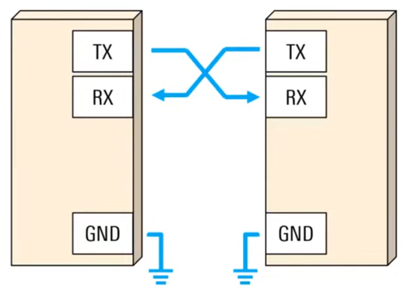
The main purpose of a transmitter and receiver line for each device is to transmit and receive serial data intended for serial communication.
- TX:Transmitter 發送端.
- RX:Receiver 接收端.
Data Framing:
The idle, no data state is high-voltage, or powered. High voltage is called "marked". Low voltage is called "space".
This is a historic legacy from telegraphy, in which the line is held high to show that the line and transmitter are not damaged.
- Start bit: changing voltage from high to low, signaling the receiver that a new data is coming
- Data bits: 5~9 bits (usually 7 or 8 bits). In most applications the least significant data bit (LSB) is transmitted first
- Parity bit: used for error detection. If the parity bit is a 0 (even parity), the 1 or logic-high bit in the data frame should total to an even number. If the parity bit is a 1 (odd parity), the 1 bit or logic highs in the data frame should total to an odd number.
- Stop bit: stay or return to high. Can have 1 or 2 stop bit, signaling the receiver that the data is complete.
Since the start bit is logic low (0) and the stop bit is logic high (1) there are always at least two guaranteed signal changes between characters. If the line is held in the logic low condition for longer than a character time, this is a break condition that can be detected by the UART.
Data Transmission
The UART interface does not use a clock signal to synchronize the transmitter and receiver devices; it transmits data asynchronously. Instead of a clock signal, the transmitter generates a bitstream based on its clock signal while the receiver is using its internal clock signal to sample the incoming data. The point of synchronization is managed by having the same baud rate on both devices. Failure to do so may affect the timing of sending and receiving data that can cause discrepancies during data handling. The allowable difference of baud rate is up to 10% before the timing of bits gets too far off. [4]
Preconfigured setting:
- Speed/Baud Rate: 4800, 9600, 19200, 57600, 115200, etc.
- Parity: none, even, odd.
- Data Bits: 5, 6, 7, 8, 9.
- Stop Bits, 1, 2.
e.g. 9600 8N1 for speed=9600, databits=8, parity=none, stopbits=1
Pros and Cons
- Advantages
- low cost, and easy construct for low speed, low throughput application
- only two wires are needed
- provide error detection mechanism (parity bit)
- Disadvantages [1]
- the size of a frame is limited to a maximum of 9 bits
- does not support multiple device communication
- low speed is the bottleneck for application which required higher data transmission rate
Demo: UART Communication with Computer
Original experiment from: https://github.com/binaryupdates/Arduino-Serial-Communication-using-UART [3]

int value = 0;

void setup() {
  Serial.begin(9600);
  pinMode(13, OUTPUT);
}

void loop() {
  if (Serial.available() > 0) {
    value = Serial.read();
    delay(5);

    if (value == '1') {
      digitalWrite(led, HIGH);
      Serial.println("LED is ON");
    }

    if (value == '0') {
      digitalWrite(led, LOW);
      Serial.println("LED is OFF");
    }
  }
}
- Arduino usb port to PC is a uart serial (COM) port, shown as /dev/cu.usbserial-1410
- Open the arduino serial monitor on PC and choose the correct frame format, then can send data through uart to arduino
LSB first v.s. MSB first
- Most significant bit (MSB) first means that the most significant bit will arrive first.
- Least significant bit (LSB) first means that the least significant bit will arrive first.
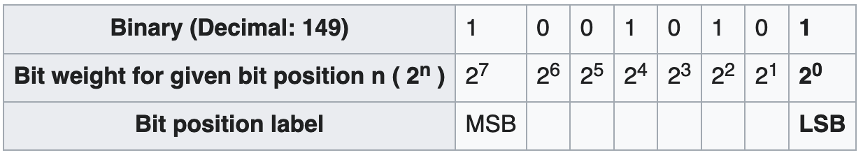
Data: B 1 0 1 0 0 1 1 (ASCII'S',0x53)
LSB (first) order: 1 1 0 0 1 0 1
MSB (first) order: 1 0 1 0 0 1 1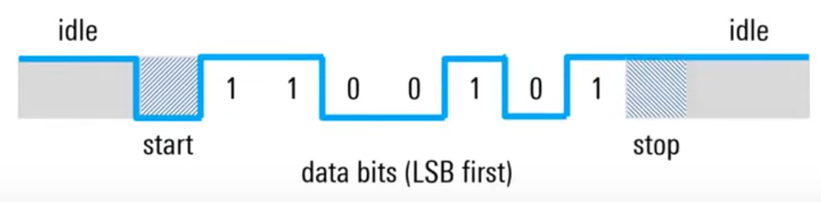
Reference
[1] https://en.wikipedia.org/wiki/Universal_asynchronous_receiver-transmitter
[2] https://www.youtube.com/watch?v=sTHckUyxwp8
[3] https://www.youtube.com/watch?v=LubYc87S9tQ
[4] https://www.analog.com/en/analog-dialogue/articles/uart-a-hardware-communication-protocol.html
Read in markdown version: https://github.com/shannon112/Notes/blob/main/UART/README.md
0 comments:
張貼留言
留言