

要開始看這些傳輸協定之前,必須先瞭解我們到底在講一個communication中的哪一段,不然很容易失焦,像是你不會想問TCP/IP用的是哪一種型號的接頭,或是拿著DP9的RS-232接頭問說這條線IP是多少,而透過OSI 7 Layer Model,一個「概念模型」,可以幫助了解和分類各個通訊協定所在的分工位置多上層多底層或是他到底是一個多大scale的東西橫跨幾層。
本篇內容大部分都是複製參考連結和Wiki的,主要是把他們整理到同一個table做比較,當然其實協定規範的不一定那麼死,像是傳輸速度或距離僅供參考,實作上其實會根據材料選擇不同而有所差異。然後table視覺沒有做得很好,可以開瀏覽器的閱讀模式(通常在網址旁邊)或參考以下:
Markdown版本:https://github.com/shannon112/Notes/blob/main/OSI_model/README.md
Open System Interconnection Model (OSI Model)
開放式系統互聯模型(Open System Interconnection Model, OSI)是一種概念模型,由國際標準化組織提出,一個試圖使各種電腦在世界範圍內互連為網路的標準框架。
The Open Systems Interconnection model (OSI model) is a conceptual model that characterises and standardises the communication functions of a telecommunication or computing system without regard to its underlying internal structure and technology. Its goal is the interoperability of diverse communication systems with standard communication protocols.
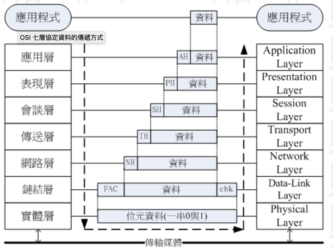
The model partitions the flow of data in a communication system into seven abstraction layers, from the physical implementation of transmitting bits across a communications medium to the highest-level representation of data of a distributed application. Each intermediate layer serves a class of functionality to the layer above it and is served by the layer below it. Classes of functionality are realized in software by standardized communication protocols. [1][2]
| Layer | Protocol data unit (PDU) | Function | Examples | |
|---|---|---|---|---|
| Host layers | 7.Application | Data | High-level APIs, including resource sharing, remote file access | DNS, FTP, HTTP, SMTP, Telnet, DHCP |
| Host layers | 6.Presentation | Data | Translation of data between a networking service and an application; including character encoding, data compression and encryption/decryption | MIME, XDR, ASN.1, ASCII, PGP |
| Host layers | 5.Session | Data | Managing communication sessions, i.e., continuous exchange of information in the form of multiple back-and-forth transmissions between two nodes | Real-time Transport Protocol (RTP) |
| Host layers | 4.Transport | Segment, Datagram | Reliable transmission of data segments between points on a network, including segmentation, acknowledgement and multiplexing | TCP, UDP |
| Media layers | 3.Network | Packet | Structuring and managing a multi-node network, including addressing, routing and traffic control | IPv4, IPv6 |
| Media layers | 2.Data link | Frame | Reliable transmission of data frames between two nodes connected by a physical layer | IEEE 802.3(Ethernet), IEEE 802.11(WIFI), MAC, ISO 11898-1(CAN) |
| Media layers | 1.Physical | Bit, Symbol | Transmission and reception of raw bit streams over a physical medium | IEEE 802.3(Ethernet), IEEE 802.11(WIFI), USB, Bluetooth, RS-232, ISO 11898-2(CAN) |
Common Protocol in Robotics Application: Overview
| I2C | SPI | RS-232(UART based) | RS-485 (UART based) | CAN | Ethernet | USB | CANOpen | EtherCAT | |
|---|---|---|---|---|---|---|---|---|---|
| 1.Physical | I2C | SPI | RS-232(EIA/TIA-232-F) | RS-485(EIA/TIA-485-A) | ISO 11898-2 | IEEE 802.3 | USB 1.1/2.0/3.0/3.1 | CAN(ISO 11898-2) | IEC 61158-> Ethernet(100BASE-TX, 100BASE-FX) |
| 2.Data-Link | I2C | SPI | UART | UART | ISO 11898-1 | IEEE 802.3 | USB 1.1/2.0/3.0/3.1 | CAN(ISO 11898-1) | IEC 61158-> Ethernet(MAC), Mailbox/Buffer Handling, Process Data Mapping, Extreme Fast Auto-Forwarder |
| 3.Network | USB 1.1/2.0/3.0/3.1 | IP (optional) | |||||||
| 4.Transport | USB 1.1/2.0/3.0/3.1 | TCP/UDP (optional) | |||||||
| 5.Session | CiA 303-1 | ||||||||
| 6.Presentation | CiA 303-2 | ||||||||
| 7.Application | CiA 401, 402, ... | standard data(1~4,7), real-time data(1~2,7) | |||||||
| * Speed | 100/400 Kbps | a few Mbps | 9.6/19.2/38.4/57.6/115.2 Kbps | a few mbps | 125 Kbps/1 Mbps | 10/10/100/1000/400000 Mbps | 1.5(12)/480/5000/10000 Mbps | 125 Kbps/1 Mbps | 100/100 Mbps |
| * Topology | Bus | Star | 1-to-1 | Daisy Chain with terminating resistors | Daisy Chain with terminating resistors | Star / Daisy Chain with terminating resistors | Star | Daisy Chain with terminating resistors | Star / Tree / Line / Bus / Ring |
| * Max # devices | 112(7bits)/1008(10bits) | multiple | 2 | 64(4-wires) / 32(2-wires) | 128 | 2(point-to-point)/30(chain) | 2(point-to-point)/127(per hub) | 128 | 65536 |
| * Max length | 1m | 0.2m | 50m | 1200m | 500 meters / 40 meters | 500/100/15/100/1000up m | 2~5 m | 500 meters / 40 meters | 100m / a few km |
| * Transfer mode | Half-Duplex | Full-Duplex | Half-Duplex | Full-Duplex(4-wires) / Half-Duplex(2-wires) | Half-Duplex | Full-Duplex | Full-Duplex(3.x) / Half-Duplex(1.x/2.x) | Half-duplex | Full-Duplex |
| * Multi-Master Support | Y | N | N | N | Y | Y | N | N | N |
RS-232
Overview: https://www.youtube.com/watch?v=eo9dbnrpspM
- Recommended Standard 232 (RS-232) is a standard originally introduced in 1960 for serial communication transmission of data.
- It formally defines signals connecting between a DTE (data terminal equipment) such as a computer terminal, and a DCE (data circuit-terminating equipment or data communication equipment), such as a modem.
- The standard defines the electrical characteristics and timing of signals, the meaning of signals, and the physical size and pinout of connectors. OSI Layer 1 Physical Layer. EIA standard RS-232-C[3] as of 1969 defines:
- Electrical signal characteristics such as voltage levels, signaling rate, timing, and slew-rate of signals, voltage withstand level, short-circuit behavior, and maximum load capacitance.
The voltage levels that correspond to logical one and logical zero levels for the data transmission and the control signal lines. Valid signals are either in the range of +3 to +15 volts(0,space) or the range −3 to −15 volts(1,mark) with respect to the "Common Ground" (GND) pin; consequently, the range between −3 to +3 volts is not a valid RS-232 level. For data transmission lines (TxD, RxD, and their secondary channel equivalents), logic one and zero is represented. Control signals have the opposite polarity: the asserted or active state is positive voltage and the de-asserted or inactive state is negative voltage. Examples of control lines include request to send (RTS), clear to send (CTS), data terminal ready (DTR), and data set ready (DSR).
- Interface mechanical characteristics, pluggable connectors and pin identification.
1.According to the standard, male connectors have DTE pin functions, and female connectors have DCE pin functions. Other devices may have any combination of connector gender and pin definitions. Many terminals were manufactured with female connectors but were sold with a cable with male connectors at each end; the terminal with its cable satisfied the recommendations in the standard.
2.The standard recommends the D-subminiature 25-pin(D-sub 25, DB25). Most devices only implement a few of the twenty signals specified in the standard, so connectors and cables with fewer pins are sufficient for most connections, more compact, and less expensive. Personal computer manufacturers replaced the DB-25M connector with the smaller DE-9M(DB-9) connector (see Serial port).
3.Presence of a 25-pin D-sub connector does not necessarily indicate an RS-232-C compliant interface.
4.The standard does not define a maximum cable length, but instead defines the maximum capacitance that a compliant drive circuit must tolerate. A widely used rule of thumb indicates that cables more than 15 m (50 ft) long will have too much capacitance, unless special cables are used. By using low-capacitance cables, communication can be maintained over larger distances up to about 300 m (1,000 ft).For longer distances, other signal standards, such as RS-422, are better suited for higher speeds. - Functions of each circuit in the interface connector.
- Standard subsets of interface circuits for selected telecom applications.
A minimal "3-wire" RS-232 connection consisting only of TX, RX, and GND, is commonly used when the full facilities of RS-232 are not required. Even a "2-wire" connection (data and ground) can be used if the data flow is one way (for example, a digital postal scale that periodically sends a weight reading, or a GPS receiver that periodically sends position, if no configuration via RS-232 is necessary). When only hardware flow control is required in addition to two-way data, the RTS and CTS lines are added in a "5-wire" version.
- The standard does not define such elements as the character encoding (i.e. ASCII, EBCDIC, or others), the framing of characters (start or stop bits, etc.), transmission order of bits, or error detection protocols. It is OSI Layer 2. The character format and transmission bit rate are set by the serial port hardware, typically a UART, which may also contain circuits to convert the internal logic levels to RS-232 compatible signal levels. The standard does not define bit rates for transmission, except that it says it is intended for bit rates lower than 20,000 bits per second.
- Electrical signal characteristics such as voltage levels, signaling rate, timing, and slew-rate of signals, voltage withstand level, short-circuit behavior, and maximum load capacitance.
- The current version of the standard is TIA-232-F Interface Between Data Terminal Equipment and Data Circuit-Terminating Equipment Employing Serial Binary Data Interchange, issued in 1997. Electronic Industries Association (EIA). The RS-232 standard had been commonly used in computer serial ports and is still widely used in industrial communication devices such as Programmable Logic Controller(PLC), Human-Machine Interface (HMI), motor driver.
- A serial port complying with the RS-232 standard was once a standard feature of many types of computers. Personal computers used them for connections not only to modems, but also to printers, computer mice, data storage, uninterruptible power supplies, and other peripheral devices.
- RS-232, when compared to later interfaces such as RS-422, RS-485 and Ethernet, has lower transmission speed, short maximum cable length, large voltage swing, large standard connectors, no multipoint capability and limited multidrop capability.
- In modern personal computers, USB has displaced RS-232 from most of its peripheral interface roles. Few computers come equipped with RS-232 ports today, so one must use either an external USB-to-RS-232 converter or an internal expansion card with one or more serial ports to connect to RS-232 peripherals.
- Nevertheless, thanks to their simplicity and past ubiquity, RS-232 interfaces are still used—particularly in industrial machines, networking equipment, and scientific instruments where a short-range, point-to-point, low-speed, inexpensive wired data connection is fully adequate.
- Hardware Interrupt:
- Ring Indicator (RI) is a signal sent from the DCE to the DTE device. It indicates to the terminal device that the phone line is ringing. In many computer serial ports, a hardware interrupt is generated when the RI signal changes state. Having support for this hardware interrupt means that a program or operating system can be informed of a change in state of the RI pin, without requiring the software to constantly "poll" the state of the pin.
- Flow control (data) § Hardware flow control:
- The Request to Send (RTS) and Clear to Send (CTS) signals were originally defined for use with half-duplex (one direction at a time) modems such as the Bell 202. These modems disable their transmitters when not required and must transmit a synchronization preamble to the receiver when they are re-enabled. The DTE asserts RTS to indicate a desire to transmit to the DCE, and in response the DCE asserts CTS to grant permission, once synchronization with the DCE at the far end is achieved. Such modems are no longer in common use. There is no corresponding signal that the DTE could use to temporarily halt incoming data from the DCE. Thus RS-232's use of the RTS and CTS signals, per the older versions of the standard, is asymmetric.
- There is a need for symmetric, bidirectional flow control. They redefined the RTS signal and defined a new signal "RTR (Ready to Receive)", shares the same pin as RTS. In this scheme, commonly called "RTS/CTS flow control" or "RTS/CTS handshaking" (though the technically correct name would be "RTR/CTS"), the DTE asserts RTR whenever it is ready to receive data from the DCE, and the DCE asserts CTS whenever it is ready to receive data from the DTE. Unlike the original use of RTS and CTS with half-duplex modems, these two signals operate independently from one another. This is an example of hardware flow control.
- Limitations:
- The large voltage swings and requirement for positive and negative supplies increases power consumption of the interface and complicates power supply design. The voltage swing requirement also limits the upper speed of a compatible interface.
- Single-ended signaling referred to a common signal ground limits the noise immunity and transmission distance.
- Multi-drop connection among more than two devices is not defined. While multi-drop "work-arounds" have been devised, they have limitations in speed and compatibility.
- The standard does not address the possibility of connecting a DTE directly to a DTE, or a DCE to a DCE. Null modem cables can be used to achieve these connections, but these are not defined by the standard, and some such cables use different connections than others.
- The definitions of the two ends of the link are asymmetric. This makes the assignment of the role of a newly developed device problematic; the designer must decide on either a DTE-like or DCE-like interface and which connector pin assignments to use.
- The handshaking and control lines of the interface are intended for the setup and takedown of a dial-up communication circuit; in particular, the use of handshake lines for flow control is not reliably implemented in many devices.
- No method is specified for sending power to a device. While a small amount of current can be extracted from the DTR and RTS lines, this is only suitable for low-power devices such as mice.
- The DB25 connector recommended in the standard is large compared to current practice.
RS-485
Overview: https://www.youtube.com/watch?v=3wgKcUDlHuM
- RS-485, also known as TIA-485(-A) or EIA-485, is a standard defining the electrical characteristics of drivers and receivers for use in serial communications systems.
- Electrical signaling is balanced, and multipoint systems are supported(multidrop communications, up to 32 devices).Inexpensive, faster, longer distance, less noise. Such as a younger brother of RS-232.
- Digital communications networks implementing the standard can be used effectively over long distances and in electrically noisy environments. Multiple receivers may be connected to such a network in a linear, multidrop bus. These characteristics make RS-485 useful in industrial control systems and similar applications such as Variable Frequency Drives(VFD or motor drives), PLC, HMI.
- Using the same differential signaling over twisted pair as RS-422. RS-485, like RS-422, can be made full-duplex by using four wires.
- It is generally accepted that RS-485 can be used with data rates up to 10 Mbit/s or, at lower speeds, distances up to 1,200 m (4,000 ft). As a rule of thumb, the speed in bit/s multiplied by the length in metres should not exceed 10^8. Thus a 50-meter cable should not signal faster than 2 Mbit/s.
- RS-485 only specifies the electrical characteristics of the generator and the receiver. OSI layer 1 the physical layer. It does not specify or recommend any communications protocol; Other standards define the protocols for communication over an RS-485 link. The foreword to the standard references The Telecommunications Systems Bulletin TSB-89 which contains application guidelines, including data signaling rate vs. cable length, stub length, and configurations.
- Section 4 defines the electrical characteristics of the generator (transmitter or driver), receiver, transceiver, and system. These characteristics include: definition of a unit load, voltage ranges, open-circuit voltages, thresholds, and transient tolerance.
- It also defines three generator interface points (signal lines); A, B and C. The data is transmitted on A and B. C is a ground reference. This section also defines the logic states 1 (off, mark) and 0 (on, space), by the polarity between A and B terminals. If A is negative with respect to B, the state is binary 1. The reversed polarity (A +, B −) is binary 0. The standard does not assign any logic function to the two states.
- In addition to the A and B connections, an optional, third connection may be present (the TIA standard requires the presence of a common return path between all circuit grounds along the balanced line for proper operation) called SC, G or reference, the common signal reference ground used by the receiver to measure the A and B voltages. This connection may be used to limit the common-mode signal that can be impressed on the receiver inputs. The allowable common-mode voltage is in the range −7V to +12V, i.e. ±7V on top of the 0-5V signal range. Failure to stay within this range will result in, at best, signal corruption, and, at worst, damage to connected devices.
- Connector types are not specified. Refer to RS-232, using DB9 connector. Cable is using balanced interconnecting cable (shielded cable) to prevent noise.
Ethernet
Overview: https://www.youtube.com/watch?v=HLziLmaYsO0
- Ethernet is a family of wired computer networking technologies commonly used in local area networks (LAN), metropolitan area networks (MAN) and wide area networks (WAN).
- It was commercially introduced in 1980 and first standardized in 1983 as IEEE 802.3, covering OSI physical layer and data-link layer.
- Ethernet has since been refined to support higher bit rates, a greater number of nodes, and longer link distances, but retains much backward compatibility. Over time, Ethernet has largely replaced competing wired LAN technologies such as Token Ring, FDDI and ARCNET.
- Physical layer: About the cabling, signaling and devices.
- The original Ethernet uses coaxial cable (10BASE5) as a shared medium, using a thick and stiff coaxial cable up to 500 meters (1,600 ft) in length. Up to 100 stations can be connected to the cable using vampire taps and share a single collision domain with 10 Mbit/s of bandwidth shared among them. The system is difficult to install and maintain. https://en.wikipedia.org/wiki/10BASE5
- The newer Ethernet variants use twisted pair (10BASE-T, 100BASE-TX, and 1000BASE-T) with 8P8C modular connectors. Correspondingly, Cat3 10Mbit/s and 100meters, Cat5e 100Mbit/s and 15meters, Cat5 1000Mbit/s and 100meters. https://en.wikipedia.org/wiki/Ethernet_over_twisted_pair
- 8P8C commonly referred to as RJ45 in the context of Ethernet and category 5 cables, RJ-45 originally refers to a specific wiring configuration of an 8P8C connector. A telephone-system-standard RJ45 plug has a key which excludes insertion in an un-keyed 8P8C socket. https://en.wikipedia.org/wiki/Modular_connector
- The newest Fiber optic (glass or plastic) with SFP and SC connector, are also very popular in larger networks, offering high performance, better electrical isolation and longer distance, run at 400Gbit/s and longer than 1000 meters. https://en.wikipedia.org/wiki/Optical_fiber
- SC(Subscriber/Square/Standard Connector) and SFP(Small Factor/Form Pluggable): https://en.wikipedia.org/wiki/Optical_fiber_connector and https://en.wikipedia.org/wiki/Small_form-factor_pluggable_transceiver
- Ethernet devices are consisting of any device which have a Network Interface Card (NIC), USB based or PCI based. https://en.wikipedia.org/wiki/Network_interface_controller
- Repeaters and hubs. For signal degradation and timing reasons, coaxial Ethernet segments have a restricted size. Somewhat larger networks can be built by using an Ethernet repeater and hub. https://en.wikipedia.org/wiki/Ethernet_hub
- Switch and Router act as a director of the network. Connecting multiple devices and enabling communication between all the devices. https://en.wikipedia.org/wiki/Network_switch and https://en.wikipedia.org/wiki/Router_(computing)
- Gateway and Bridge are used to connect multiple Ethernet network together, allow communication across them. Gateway connects two dissimilar network together. Bridge connects two similar network together. https://en.wikipedia.org/wiki/Gateway_(telecommunications) and https://en.wikipedia.org/wiki/Bridging_(networking)
- Data-link layer: Including framing, media access control(MAC) and logical link control(LLC).
- Logical Link Control(LLC): The LLC establishes paths for data on the Ethernet to transmit between devices. The LLC sublayer provides multiplexing mechanisms that make it possible for several network protocols to coexist within a multipoint network and to be transported over the same network medium. Since bit errors are very rare in wired networks, Ethernet does not provide flow control or automatic repeat request (ARQ), meaning that incorrect packets are detected but only cancelled, not retransmitted (except in case of collisions detected by the CSMA/CD MAC layer protocol). Instead, retransmissions rely on higher layer protocols. https://en.wikipedia.org/wiki/Logical_link_control
- Media Access Control(MAC): The Media Access Control uses hardware addresses that are assigned to Network Interface Cards (NIC) to identify a specific computer or device to show the source and destination of data transmissions. The 48-bit MAC address was adopted by other IEEE 802 networking standards, including IEEE 802.11 (Wi-Fi), as well as by FDDI. https://en.wikipedia.org/wiki/Medium_access_control
- The frame begins after the start frame delimiter with a frame header featuring source and destination MAC addresses and the EtherType field giving either the protocol type for the payload protocol or the length of the payload. The middle section of the frame consists of payload data including any headers for other protocols (for example, Internet Protocol) carried in the frame. The frame ends with a 32-bit cyclic redundancy check(CRC), which is used to detect corruption of data in transit. Notably, Ethernet packets have no time-to-live field, leading to possible problems in the presence of a switching loop. https://en.wikipedia.org/wiki/Ethernet_frame and https://en.wikipedia.org/wiki/Cyclic_redundancy_check.
- CSMA/CD is used as a standard for Ethernet to reduce data collisions and increase successful data transmission. The algorithm first checks to see if there is traffic on the network. If it does not find any, it will send out the first bit of information to see if a collision will occur. If this first bit is successful, then it will send out the other bits while still testing for collisions. If a collision occurs, the algorithm calculates a waiting time and then starts the process all over again until the full transmission is complete. https://en.wikipedia.org/wiki/Carrier-sense_multiple_access
- Ethernet is widely used in homes and industry, and interworks well with wireless Wi-Fi technologies. The Internet Protocol is commonly carried over Ethernet and so it is considered one of the key technologies that make up the Internet.
EtherCAT
Overview: https://www.youtube.com/watch?v=tYAl2jkaB8Q
- EtherCAT (Ethernet for Control Automation Technology) is an Ethernet-based fieldbus system, invented by Beckhoff Automation. The protocol is standardized in IEC 61158 and is suitable for both hard and soft real-time computing requirements in automation technology.
- Fieldbus is the name of a family of industrial computer networks used for real-time distributed control. Fieldbus profiles are standardized by the International Electrotechnical Commission (IEC) as IEC 61784/61158. https://en.wikipedia.org/wiki/Fieldbus
- The goal during development of EtherCAT was to apply Ethernet for automation applications requiring 1.short data update times (also called cycle times; ≤ 100 μs) with low communication jitter (for precise synchronization purposes; ≤ 1 μs) and 2.reduced hardware costs.
- "On the fly": With EtherCAT, the standard Ethernet packet or frame (according to IEEE 802.3) is no longer received, interpreted, and copied as process data at every node(several frames). The bandwidth and real-time are the problem if working in Ethernet mode. The EtherCAT slave devices read the data addressed to them while the telegram(one frame) passes through the device, processing data "on the fly". In other words, real-time data and messages are prioritized over more general, less time-sensitive or heavy load data. Similarly, input data are inserted while the telegram passes through. A frame is not completely received before being processed; instead processing starts as soon as possible. Sending is also conducted with a minimum delay of small bit times. Typically the entire network can be addressed with just one frame.
- Compatible Speed: Although there is still a small delay in the data frame as the device adds its data to it, it is greatly reduced by the often single data stream of EtherCAT versus the multiple Ethernet frames used in an Ethernet network. This advantage can also be a disadvantage. Many devices may not be able to handle these highly decreased cycle times and EtherCAT network may need to be slowed to accommodate these devices. Since the EtherCAT network can be slowed, mark the disadvantage as an advantage once again.
- Distributed Clock System: EtherCAT also utilizes a distributed clock system. This method allows for low jitter without additional hardware and it meets with the synchronization importance desired in industrial automation. As the EtherCAT frame passes through each node, the node adds a “received message” timestamp to its data. Each node adds the timestamp as the message is received and then, each node again attaches a timestamp as the frame moves back through the nodes, on the way back to the master. The master then has an accurate delay for each node as timestamp data is calculated with every data frame transmission. With EtherCAT’s intrinsic ring topology, this ensures increasingly accurate data with every data transmission because of the distributed clock mechanism.
- Topology: Each EtherCAT device typically has two Ethernet ports, the first port being the receiving port or previous node’s cable and the second port connected to the next node in the network. It utilizes Ethernets full duplex layers, the EtherCAT slave will automatically return the frame, to the master, with an open port detected downstream, essentially, self-terminating. Ethernet’s star topology is simple and can be used but EtherCAT networks can extend well beyond that with a tree, line, ring, etc. It can also be used in a Fieldbus type system using Ethernet hardware, giving incredible flexibility for your EtherCAT network.
- Redundancy Using Ring Topology: Considering the inherent “ring technology” of EtherCAT, connecting the network in a ring topology would be a “redundant system” if you can imagine. Because it’s inherently a ring topology, connecting the master’s second port, if available, would provide redundancy on the other side of the network break. Each topology type should be investigated for your network to conclude which solution would be best for your application.
CAN
Overview: https://www.youtube.com/watch?v=FqLDpHsxvf8
- A Controller Area Network (CAN bus) is a robust vehicle bus standard designed to allow microcontrollers and devices to communicate with each other's applications without a host computer. A car is like a human body. CAN bus is the nervous system, enabling communication. In turn, 'nodes' or 'ECUs" are like parts of the body, interconnected via the CAN bus. Information sensed by one part can be shared with another.
- In an automotive CAN bus system, electronic control units (ECUs) can e.g. be the engine control unit, airbags, audio system etc. A modern car may have up to 70 ECUs - and each of them may have information that needs to be shared with other parts of the network. https://en.wikipedia.org/wiki/Electronic_control_unit
- 1.Simple & low cost: It is a message-based protocol, designed originally for multiplex electrical wiring within automobiles to save on copper, but can also be used in many other contexts. The CAN bus system enables each ECU to communicate with all other ECUs - without complex dedicated wiring. ECUs communicate via a single CAN system instead of via direct complex analogue signal lines - reducing errors, weight, wiring and costs
- 2.Fully centralized: The CAN bus provides 'one point-of-entry' to communicate with all network ECUs - enabling central diagnostics, data logging and configuration
- Frames are received by all devices, including by the transmitting device. Specifically, an ECU can prepare and broadcast information (e.g. sensor data) via the CAN bus (consisting of two wires, CAN low and CAN high). The broadcasted data is accepted by all other ECUs on the CAN network - and each ECU can then check the data and decide whether to receive or ignore it.
- 3.Extremely robust: The system is robust towards electric disturbances and electromagnetic interference - ideal for safety critical applications (e.g. vehicles)
- 4.Efficient: CAN frames are prioritized by ID so that top priority data gets immediate bus access, without causing interruption of other frames. For each device the data in a frame is transmitted sequentially but in such a way that if more than one device transmits at the same time the highest priority device is able to continue while the others back off.
- History: Pre CAN: Car ECUs relied on complex point-to-point wiring. 1986: Bosch developed the CAN protocol as a solution. 1993: CAN is adopted as international standard (ISO 11898). 2015: The CAN FD protocol is standardized (ISO 11898-1). 2016: The physical CAN layer for data-rates up to 5 Mbit/s standardized in ISO 11898-2. Today, CAN is standard in automotives (cars, trucks, buses, industrial vehicle,...), industrial automation, ships, planes, EV batteries, machinery, drone, submarines, radar systems, robotics and more.
- ISO 11898-1 describes the data link layer: A standard CAN frame with 11 bits identifier (CAN 2.0A), which is the type used in most cars. The extended 29-bit identifier frame (CAN 2.0B) is identical except the longer ID. Note that the CAN ID, Control and Data are highlighted - these are important when recording CAN bus data.
- SOF: The Start of Frame is a 'dominant 0' to tell the other nodes that a CAN node intends to talk
- ID: The ID is the frame identifier - lower values have higher priority
- RTR: The Remote Transmission Request indicates whether a node sends data or requests dedicated data from another node
- Control: The Control contains the Identifier Extension Bit (IDE) which is a 'dominant 0' for 11-bit. It also contains the 4 bit Data Length Code (DLC) that specifies the length of the data bytes to be transmitted (0 to 8 bytes)
- Data: The Data contains the data bytes aka payload, which includes CAN signals that can be extracted and decoded for information
- CRC: The Cyclic Redundancy Check is used to ensure data integrity
- ACK: The ACK slot indicates if the node has acknowledged and received the data correctly
- EOF: The EOF marks the end of the CAN frame
- ISO 11898-2 describes the physical layer: 1.Baud rate: CAN nodes must be connected via a two wire bus with baud rates up to 1 Mbit/s (Classical CAN) or 5 Mbit/s (CAN FD). 2.Cable length: Maximal CAN cable lengths should be between 500 meters (125 kbit/s) and 40 meters (1 Mbit/s). 3.Termination: The CAN bus must be properly terminated using a 120 Ohms CAN bus termination resistor at each end of the bus
- How to log CAN bus data? As mentioned, two CAN fields are important for CAN logging: The CAN ID and the Data. To record CAN data you need a CAN logger. This lets you log timestamped CAN data to an SD card. In some cases, you need a CAN interface to stream data to a PC - e.g. for car hacking.
- The CAN provides the basis for communication - but not a lot more. For example, the CAN standard does not specify how to handle messages larger than 8 bytes - or how to decode the raw data. Therefore a set of standardized protocols exist to further specify how data is communicated between CAN nodes of a given network. Some of the most common standards include SAE J1939, OBD2 and CANopen. Further, these higher-layer protocols will increasingly be based on the 'next generation' of CAN, CAN FD (e.g. CANopen FD and J1939-17/22).
- CANopen is used widely in embedded control applications, incl. e.g. industrial automation. It is based on CAN, meaning that a CAN bus data logger is also able to log CANopen data. This is key in e.g. machine diagnostics or optimizing production.
CANOpen
Overview: https://www.youtube.com/watch?v=DlbkWryzJqg
- CANopen is a CAN based communication protocol and device profile specification. The CANopen standard is useful as it enables off-the-shelf interoperability between devices (nodes) in e.g. industrial machinery. Further, it provides standard methods for configuring devices - also after installation. CANopen was originally designed for motion-oriented machine control systems. Today, CANopen is extensively used in motor control (stepper/servomotors) - but also a wide range of other applications: Robotics, Medical, Automotive.
- In terms of the OSI model, CANopen implements the layers above and including the network layer. The CANopen standard consists of an addressing scheme, several small communication protocols and an application layer defined by a device profile. The communication protocols have support for network management, device monitoring and communication between nodes, including a simple transport layer for message segmentation/desegmentation. The lower level protocol implementing the data link and physical layers is usually Controller Area Network (CAN), although devices using some other means of communication (such as Ethernet Powerlink, EtherCAT) can also implement the CANopen device profile.
- The basic CANopen device and communication profiles are given in the CiA 301 specification released by CAN in Automation. Profiles for more specialized devices are built on top of this basic profile, and are specified in numerous other standards released by CAN in Automation, such as CiA 401 for I/O-modules and CiA 402 for motion control.
- There are six core CANopen concepts:
- 1.Communication Models: There are 3 models for device/node communication: Master/slave, client/server and producer/consumer.
- Master/Slave: One node (e.g. the control interface) acts as application master or host controller. It sends/requests data from the slaves (e.g. the servo motors). This is used in e.g. diagnostics or state management. There can be 0-127 slaves in standard applications. Note that in a single CANopen network, there can be different host controllers sharing the same data link layer.
- Client/Server[SDO]: A client sends a data request to a server, which replies with the requested data. Used e.g. when an application master needs data from the OD of a slave. A read from a server is an “upload”, while a write is a “download” (the terminology takes a "server side" perspective).
- Consumer/Producer[PDO]: Here, the producer node broadcasts data to the network, which is consumed by the consumer node. The producer either sends this data on request (pull model) or without a specific request (push model).
- The CANopen frame: COB-ID+RTR+Data_length+Data. The 11-bit CAN ID is referred to as the Communication Object Identifier (COB-ID) and is split in two parts: the first 4 bits equal a function code and the next 7 bits contain the node ID. The COB-IDs (e.g. 381, 581, …) are linked to the communication services (transmit PDO 3, transmit SDO, …). As such, the COB-ID details which node is sending/receiving data - and what service is used.
- 2.Communication Protocols: Protocols are used for communication, e.g. configuring nodes (SDOs) or transmitting real-time data (PDOs).
- Network Management (NMT): The NMT service is used for controlling the state of CANopen devices (e.g. pre-operational, operational, stopped) by means of NMT commands (e.g. start, stop, reset).
- Synchronization (SYNC): The SYNC message is used e.g. to synchronize the sensing of inputs and actuation of several CANopen devices - typically triggered by the application master.
- Emergency (EMCY): The emergency service is used in case a device experiences a fatal error (e.g. a sensor failure), allowing it to indicate this to the rest of the network.
- Timestamp(TIME)[PDO]: With this communication service a global network time can be distributed. The TIME service contains a 6-byte date & time information.
- Proccess Data Object[PDO]: The PDO service is used to transmit real-time data between devices - e.g. measured data such as position or command data such as torque requests.
- Service Data Object[SDO]: The SDO services are used to access/change values in the object dictionary of a CANopen device - e.g. when an application master needs to change certain configurations of a CANopen device.
- Node monitoring(Heartbeat)[SDO]: The Heartbeat service has two purposes: To provide an 'alive' message and to confirm the NMT command.
- 3.Device States: A device supports different states. A 'master' node can change state of a 'slave' node - e.g. resetting it.
- 4.Object Dictionary(OD): Each device must has an OD with entries that specify e.g. the device config. It can be accessed via SDOs.
- The object dictionary is a standardized structure containing all parameters describing the behavior of a CANopen node.
- OD entries are looked up via a 16-bit index(4 digits hex) and 8-bit subindex(2 digits hex). For example, index 1008 (subindex 0) of a CANopen-compliant node OD contains the node device name.
- Specifically, an entry in the object dictionary is defined by attributes: Index: 16-bit base address of the object, Object name: Manufacturer device name, Object code: Array, variable, or record, Data type: E.g. VISIBLE_STRING, or UNSIGNED32 or Record Name, Access: rw (read/write), ro (read-only), wo (write-only), Category: Indicates if this parameter is mandatory/optional (M/O)
- OD standardized sections: The object dictionary is split into standardized sections where some entries are mandatory and others are fully customizable. Importantly, OD entries of a device (e.g. a slave) can be accessed by another device (e.g. a master) via CAN using e.g. SDOs. For example, this might let an application master change whether a slave node logs data via a specific input sensor - or how often the slave sends a heartbeat.
- 5.Electronic Data Sheet(EDS): The EDS is a standard file format for OD entries - allowing e.g. service tools to update devices.
- To simplify this, the CiA 306 standard defines a human-readable (and machine friendly) INI file format, acting as a "template" for the OD of a device - e.g. the “ServoMotor3000”. This EDS is typically provided by the vendor and contains info on all device objects (but not values).
- 6.Device Configuration Profiles(DCF): Standards describe e.g. I/O modules (CiA 401) and motion-control (CiA 402) for vendor independence.
- Assume a factory has bought a ServoMotor3000 to integrate into their conveyor belt. In doing so, the operator edits the device EDS and adds specific parameter values and/or changes the names of each object described in the EDS. In doing so, the operator effectively creates what is known as a Device Configuration File (DCF). With this in place, the ServoMotor3000 is ready for integration into the specific CANopen network on-site.
- The SDO service allows a CANopen node to read/edit values of another node’s object dictionary over the CAN network. As mentioned under 'communication models', the CANopen SDO services utilize a "client/server" behavior. Specifically, an SDO "client" initiates the communication with one dedicated SDO "server". The purpose can be to update an OD entry (called an "SDO download") or read an entry ("SDO upload"). In simple master/slave networks, the node with NMT master functionality acts as the client for all NMT slave nodes(select one as a server, ignore the others) reading or writing to their ODs.
- SDOs are flexible, but carry a lot of overhead - making them less ideal for real-time operational data.
- The CANopen PDO service is used for effectively sharing real-time operational data across CANopen nodes. For example, the PDO would carry pressure data from a pressure transducer - or temperature data from a temperature sensor.
- Can’t the SDO service just do this? Yes, in principle the SDO service could be used for this. However, a single SDO response can only carry 4 data bytes due to overhead (command byte and OD addresses).
- In contrast, a PDO message can contain 8 full bytes of data - and it can contain multiple object parameter values within a single frame. Thus, what would require at least 4 frames with SDO could potentially be done with 1 frame in the PDO service.
- The PDO is often seen as the most important CANopen protocol as it carries the bulk of information.
I2C, SPI, UART
Read the details in:
- Comparison: https://shannon112.blogspot.com/2021/01/embedded-system-serial-communication.html
- SPI: https://shannon112.blogspot.com/2021/01/embedded-system-serial-peripheral.html
- I2C: https://shannon112.blogspot.com/2021/01/embedded-system-inter-integrated.html
- UART: https://shannon112.blogspot.com/2021/01/embedded-system-universal-asynchronous.html
Reference
[1] https://en.wikipedia.org/wiki/OSI_model
[2] http://linux.vbird.org/linux_server/0110network_basic.php#whatisnetwork_what
[3] https://en.wikipedia.org/wiki/RS-232
[4] https://en.wikipedia.org/wiki/D-subminiature
[5] https://en.wikipedia.org/wiki/Multidrop_bus
[6] https://en.wikipedia.org/wiki/RS-485
[7] https://en.wikipedia.org/wiki/Shielded_cable
[8] https://en.wikipedia.org/wiki/Balanced_line
[9] https://en.wikipedia.org/wiki/Ethernet
[10] https://www.geeksforgeeks.org/network-devices-hub-repeater-bridge-switch-router-gateways/
[11] https://en.wikipedia.org/wiki/EtherCAT
[12] https://en.wikipedia.org/wiki/USB
[13] USB3.1: https://www.synopsys.com/designware-ip/technical-bulletin/protocol-layer-changes.html
[14] https://en.wikipedia.org/wiki/CAN_bus
[15] https://www.csselectronics.com/screen/page/simple-intro-to-can-bus
[16] https://en.wikipedia.org/wiki/CANopen
[17] https://www.csselectronics.com/screen/page/canopen-tutorial-simple-intro
[] EtherCAT v.s. CANOpen: https://dewesoft.com/daq/what-is-ethercat-protocol
[] EtherCAT v.s. CANOpen v.s RS: https://blog.servo2go.com/2013/09/23/comparing-canopen-and-ethercat-fieldbus-networks/
[] Ethernet v.s. CAN v.s. RS v.s USB v.s LIN: http://ucpros.com/work%20samples/Microcontroller%20Communication%20Interfaces%203.htm
[] Inspired from: https://blog.csdn.net/djl806943371/article/details/89331048
I appreciate your article. You truly share relevant and extraordinary knowledge. Thank you for keep sharing these valuable thoughts.
回覆刪除ETHNT POS RNG PRNT CD
1ESS X.25 DATA LINK
EQUALIZING CIRCUIT